Automatically Scored Cornhole - Scorecorn - Part 2
- ZackW
- Aug 30, 2022
- 10 min read
Updated: Sep 20, 2022
This is part 2 of my capstone saga, where me and my 2 classmates build a system to automatically score the game "Cornhole". I was focused on the Ultra WideBand ranging code in this post, trying to get the DW1000 boards from Qorvo to work how we need them.
Getting a Seeeduino Xiao to work with the DWM1000
The little corn-filled bags used to toss at the boards have to be tracked via the UWB ranging. They're meant to have little boards mounted inside of them that function as a 'tag' in the sequence. Both boards will have at least one anchor.
The Xiao uses a SAMD21G18 ARM microcontroller, one that I've used quite a bit in the past since it's on a few different development boards. So, this shouldn't be too bad since I've had to go through the SPI circus a few times with this device. To begin with, the wiring is much easier since we don't need a level converter. I wired up the Xiao directly to one of my DWM1000 development boards and started debugging.
It was already reporting it's ID almost right away, which was a good sign. I mixed up some wires and had to fix that, but then I had an issue with an unreliable connection to the DW1000. It would sometimes report the correct ID, and sometimes a garbled one. I traced this back to the power supply, which was hooked up wrong. The DWM1000 shields have a 3.3v regulator onboard, meant to down-convert from 5v. I was feeding it 3.3v, and was ending up with about 2.2v to run the DW1000. After I fixed that, the communication was much more reliable and the IRQ line started to come alive.

At this point I suspected that the DW1000 library can't correctly initiate pin interrupts on a SAMD21 processor. I made a quick test program to make sure the interrupts were working, and ran it.

Well, it did work. The syntax was essentially the same as used in the DW1000 library, so it should technically be working. The next thing to check is if the messaging application works between the two devices I'm testing. The Uno and Seeeduino Xiao can't range to eachother, but maybe the simple message example will work.

And voila, it does work. That still sounds like my IRQ pin isn't firing correctly, but it could be something else. I do know it's unlikely the Xiao can supply enough current to the DW1000, but I'm hoping the capacitors will store enough energy to run for short duty cycle transmissions. That was the case with the other Arduinos, at least. Oh hey, I reloaded the ranging example code, ran it, and it works now. Must have needed a reset or something!

This time I grabbed a tape measure to test the accuracy. I measured about 44 inches, which is 1.17m. It looked like the average error was something like 0.16m, or about 6 inches. Hopefully it's better than that in general, but that might work. If there's just an offset, we can program that in and compensate for it.
Multiple Anchors per Tag
I originally titled this "Multiple tags per Anchor" but in reality it seemed difficult to achieve that. A 'Tag' refers to the radio which transmits the poll message, asking an anchor to report how long the delay was. Having all of our game bags be tags would mean we would have to have them negotiate when to transmit. This isn't impossible, and is discussed at length in this github issue thread. I want to avoid implementing a specialized timing protocol if I can however, and some people's implementations required long wait times which would make ranging fast enough to detect throws and impacts, impractical. An on-event ranging system would probably work great, if the tags included something like an accelerometer they could range when a throw was detected. Simply having one tag and multiple anchors seems like the fastest approach, so that's what I'm going to try first.
In following with lessons learned earlier, I made sure to read as much about multiple anchors as I could. This blog post is an excellent explanation of a 3 anchor, 1 tag approach. Amusingly, to prevent transmission collisions in the pairing stage the anchors simply wait a random amount of time and hope they don't try to transmit at once. It looks like that's just a problem for pairing, since the ranging packets can be addressed to individual anchors. I'm sure that approach works fine, and it would most likely be simple to implement a search-for-n-anchors protocol that keeps pinging until it finds all the required devices.
Each game board needs to read the distance to 8 bags. The bags can be thrown in any order, but are thrown one at a time.
Quick Math
Establishing some basic physics of the game is required at this point in order to calculate how fast we need to sample the range to each bag. In a tournament, the average time it took for 3 throws to traverse between the game boards was 1.33 seconds. The official cornhole rules state the boards are 27ft apart from tip to tip. This means the bags are traveling somewhere around 20ft/s.
We have about 1.33 seconds to check 8 bags to know whether or not they've been thrown. It's hard to know the minimum number of required samples, but ideally we could check at least 3 samples in order to average them and throw out bad single samples due to movement of the players. Getting 3 samples per bag means 24 samples, in 1.33 seconds that would require a sample rate of about 55ms.
APS2013 states the shortest transmission time allowed is 1ms, so in theory if we can achieve anywhere near that poll rate we should be able to poll the bags (anchors) much faster than is necessary. According to the datasheet and APS013, the anchors actually spend more time in receive mode and theoretically also therefore use more power. This is a bit unfortunate, since they will be battery powered with very limited batteries.
Examining Existing Examples
There are 4 example code files available from the DW1000-ng Arduino library. These are:
StandardRTLSTag_TWR
StandardRTLSAnchorMain_TWR
StandardRTLSAnchorC_TWR
StandardRTLSAnchorB_TWR
(At the time of writing). This seems to be an example implementation of a multi-anchor set up, complete with a trilateration algorithm. These examples are labeled as "RTLS", which stands for Real Time Location System. It's about what you'd expect, a system that can determine location of something in real time. The real use of this term in the code seems to be the network ID, RTLS_APP_ID, which is a built-in address of the DW1000-ng library; and in some of the ranging code between anchors.
RTLS is a new search term to use actually, so I went and looked around for more documentation of this. There are some interesting projects, and a digikey page about it, but it doesn't look like anything terribly useful compared to what I've already found. What we're doing isn't actually RTLS anyway, since we are sticking with a single distance dimension and don't need to calculate our 2D or 3D position.
Back in the example code, it seems there is some sort of system to sort out which anchor is supposed to be listening to the tag at a time. The core of this seems to be the DW1000NgRTLS::anchorRangeAccept() method, which is a fairly complex bit of code to dissect. From a 30 thousand food view, it appears to handle both the polling messages to and from the tag and the ranging messages. It's sort of implied in this code that the anchor is listening the entire time for the message from the tag. There also doesn't seem to be any discriminating code for checking who the message was addressed to.
Note: I'm wrong here, the packets are directed to specific addresses.
My first thought was that the discrimination must be automatic and done by the DW1000 itself. I looked at the receive code though, and wasn't getting that impression. The tag transmit code also doesn't seem to target a specific anchor either. So, I went looking at the library wiki (sparse as it is) and the DW1000 documentation for the answer. I found figure 39 in the user manual based on a bit of text from the wiki:

As you might have guessed, the only(?) remaining method to address a specific anchor is to use a time difference. There are different delays set in the anchor examples, which must be how they don't overlap their responses. What's weird, is the anchorRangeAccept() method doesn't appear to have any kind of delay when transmitting an poll-ack.
It was at this point I went back over the protocol and discovered the the packets should indeed be directed to specific anchors from the tag. The destination address is bytes 5&6 of a frame according to APS013. I started adding comments to the library code to make following each step a little easier.
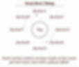
Best I can tell, this image shows how the RTLS examples work:

This doesn't show how anchor B and C pass their measurements to the main anchor; but that appears to be a simple case of joining a separate network and sending the data to the main anchor via a normal data transmission. That's actually what the delays are for in the anchor code, so the range reports don't overlap (I believe).
This is actually not super useful for what we want to do with our application. First of all, I don't think the final "poll response" message from the anchor is strictly necessary. Secondly, the anchors are in receive mode for most of the time. Having the anchors actively listening for messages from the tag is going to eat a lot of power.
Ideal Implementation
Based on what I've learned so far, I feel as if I can probably come up with an ideal implementation of ranging using these devices. Even though there is the most information available for multi-anchor systems, it seems the most efficient to actually have a multi-tag system. The tags would be the devices mounted in the game bags to be tossed. They would operate on a low duty cycle timer, polling the primary anchor in a loop.

The Anchor could even be in charge of setting up the timing, passing the information along to the tags in the setup phrase. The tags would only transmit their poll message when it was their turn, and wouldn't spend extra time waiting in receive mode.
Preventing phase drift: In reality, the phase offset of each tag would slowly drift over time and if left uncompensated would result in tags trying to transmit at the same time, or missing their slot entirely. The first method that comes to mind is to communicate the drift to the tags so they can automatically compensate for it. This could be done by having the anchor keep track of the next expected time the tag should transmit, and communicating that back to each tag. I think this would still require the use of an extra message frame.
Another option for preventing phase drift would be to use some kind of error-based correction. One possible approach would be to have the bags all re-synchronize upon an error. This would mean there would be potentially random interrupts in operation while everything synchronizes. This kind of approach would be the only one so far that only needs 3 messages per ranging, I believe.
The next best thing would probably be to use the same general implementation, but keep with the idea of multiple anchors and one tag. The anchors would enter receive mode when it was their turn, and instead of having to communicate the measured phase drift with an extra transmission, the anchors would base their next receive window on when they actually complete a ranging request. If they encounter a problem, they can simply enter a constant receive mode long enough to catch at least one full cycle and try to re-sync that way.
Programming
In writing the actual implementation, one of the things I want to avoid is a lot of cryptic calls to the DW1000 library methods. The setup and management of the devices will be hidden away in simpler functions to manage, and hopefully I can also use this approach to re-use code between the anchor and tag (and potentially data communication).
I made a new Arduino project and opened it up in Atom, my lightweight IDE of choice for Arduino stuff. I'm using VS Code for examining and editing the DW1000Ng library, since it's easier to reverse engineer in there. Most of anchor code is copied from the TwoWayRangingResponder example, but it's organized differently.

Splitting the DW1000 code into AnchorWrap.cpp and AnchorWrap.hpp helps with keeping the main sketch clean; and it helps me keep track of what's going on. I also added a simple checkDeviceId() function to the DW1000 library, which helps just a little in diagnosing if the SPI bus is working.
For now I will be using the same messaging format as is used in the example code. The tag sends a POLL, the anchor sends a response, the tag sends a RANGE, and the anchor responds with a range report. I'm not sure what the function of pairing is, since it seems to not be necessary to the example code.
I've decided to actually leave out most of the details in programming. It's a lot of copying and slight reformatting, nothing too difficult. Once I had the basic functions working, I needed a way to implement things like timeouts and timers. This isn't difficult to do with built-in Arduino functions like millis() and delay(), but isn't terribly elegant or scaleable. I found this simple task scheduling library which helped a lot with all things timing. In the end, it seems to take somewhere between 5 and 6ms to do a complete range measurement. This is fine, since we can scan all 8 bags at about 20Hz. We actually have a lot of headroom left for other multi-device ranging techniques if we want.
Lessons Learned
This was honestly a lot of grunt work, a lot of studying code and hardware and a lot of fairly straightforward programming. I can sort of say that I actually "learned" questions; in other words I have more questions now. I need to keep studying how the messaging protocol works in the DW1000 devices. I would like to write a short post on UWB ranging when I understand things a bit better.
I did really enjoy learning how to use the task scheduler library, since it will be useful for the rest of this project and also many other projects in the future. I have used RTOS's before for task scheduling, but that library is very lightweight and purpose-built. It works well on the less powerful AVR processors in addition to the ARM platforms. For an AVR processor (atmega328p), it seemed to add ~3kB to the the program size. I didn't really measure before and after directly, that's just an estimate.
To make the programming easier in the future, I think it would be nice if there were more graphics explaining how some of the time calculations work. Citing a datasheet or manual, along with a figure number or page number, when writing code could have saved me some time. I will think about including that as I program.